DTCD Measures Up
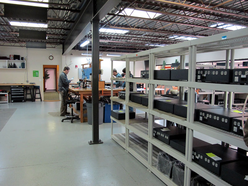
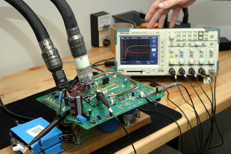
No need to feel sorry for him, though. Life is good in tiny Poulsbo, WA (population around 8000). Shunyata Research, Gabriel’s company, occupies an impressively large, modern, multi-story standalone glass-facade building in an attractive industrial park, and business is brisk despite the weak economy.
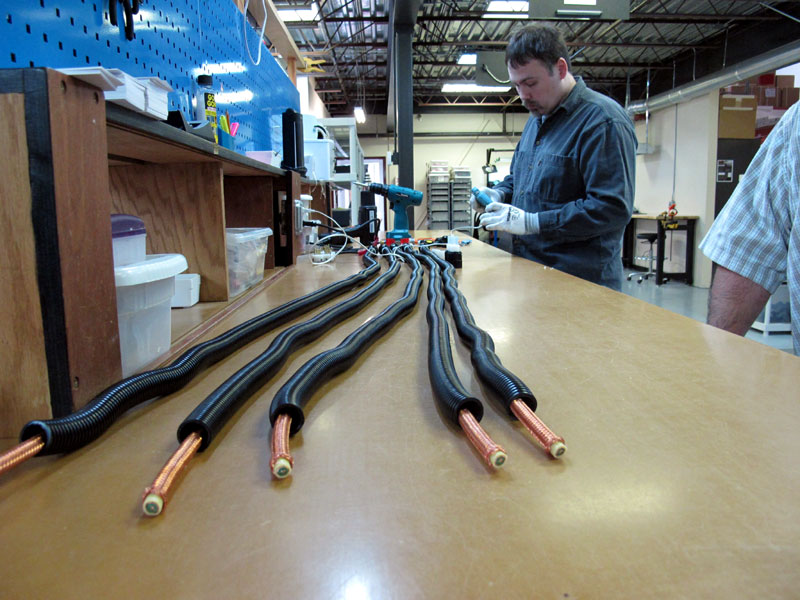
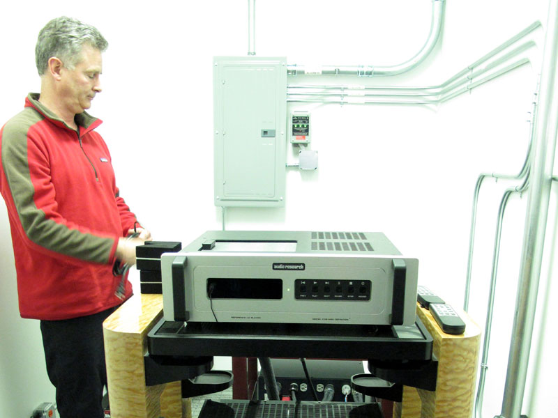
Caelin Gabriel in Shunyata Research's electronics room. Upstairs are offices, research space and an impeccably designed and equipped listening room, with special attention paid, not surprisingly, to the AC that supplies the system, the facilities for which are located in an adjacent room that also contains the system’s electronics. Downstairs are a spacious, well-equipped and clean-as-a-hospital-operating-room manufacturing facility and a large warehouse stacked floor to ceiling with inventory that I was assured doesn’t gather dust. Also not gathering dust was a cryogenic freezer that Gabriel says definitely affects the sonics of wire and connectors processed therein. Even skeptics who would be appalled to find such apparent manufacturing wealth produced by a "phony" industry trafficking in "magic power cords" and "glorified power strips" would be impressed by Shunyata’s physical plant.
For those convinced that power cords and power-distribution devices produce significant sonic differences, visiting a facility like Shunyata’s and seeing conditioners and cords being manufactured (and in large quantities) for the world’s various jack and plug configurations provides convincing affirmation that audiophiles everywhere hear and appreciate the obvious benefits of clean power as well as the seemingly unlikely sonic improvements wrought by swapping out the anonymous black molded AC cords supplied with most audio gear for ones designed and produced by a specialty manufacturer. Power-cord skeptics say things like "Power comes from the power plant, through transmission lines to a substation, then to a transformer on your street (or worse, to an apartment-building mangle), to your circuit-breaker box, and from there to an AC wall jack, and you’re telling me the last three feet of a power cord are going to make a difference?" No point, then, in putting a water filter at the end of your faucet either. The water comes from the reservoir, through a long series of old pipes, to a pumping station, to a processing facility, through a main to distribution channels and finally into your house, then through the pipes to the faucet. And you’re telling me a filter at the very end of that long journey is going to make a difference? It’s easy to see the residue and yellowing of a spent water filter, but what about AC power? That’s been the problem for purveyors of power cords and conditioners for as long as they have been manufacturing them, even as audiophiles (not to mention manufacturers) swear they can hear differences among them. Shunyata Research develops DTCD hough Shunyata Research founder Caelin Gabriel now works in a field many consider the playground of charlatans (particularly the anonymous know-nothings who troll and post on the Internet), his résumé includes being recruited by a military division of the NSA (National Security Agency), where he was involved in developing electronics designed to acquire and encode transmitted low-level digital data. Part of the training included power-supply design. He went on to research sound and its effects on human physiology and later was involved in the computer industry, specifically in the area of high-speed networking electronics. In other words, he’s not a company frontman who hired an electronics guy to design for him a power conditioner and a line of cables. Instead, he’s "da man," though of course others are involved in the creation of the company’s products. So its not surprising to hear that Gabriel has a reputation among some as a guy who doesn’t suffer fools. He can come across as arrogant -- at least among those who confuse arrogance with confidence. I found him brimming with the later and not at all the former. I’ve also seen him at CESes, where he’s not afraid to tell time-wasters where to go. But he’s read what the skeptics have to say and no doubt doesn’t like being called a charlatan or lumped in with those who actually are. So he set about designing a measuring device that could prove the claims he makes for his products and that he was certain could be measured. That device is the DTCD Analyzer, with DTCD being an acronym for "dynamic transient current delivery." After touring the company’s aforementioned facilities, I was taken to a room to see the DTCD prototype that’s functional but still being fine-tuned. I was told it has run "for days without failure" and that the plan, once the device is fully operational, is to take it from the breadboard stage to a finished product that will be marketed to other manufacturers -- and to reviewers or even consumers, should there be interest. While skeptics claim you can’t measure power-cord differences, Gabriel says otherwise. He explained that the usual measurement methodology that produces capacitance and inductance figures is to get a really long length of wire on a big spool and measure it using a capacitive/inductive analyzer, dividing the result by the number of feet in the spool. "We can actually measure in real time, very short pieces of wire and see differences," he told me, adding, "We can measure contacts, we can measure switches, we can measure fuses. Anything that conducts current in power, we can measure and we can see the differences between them. We can actually measure the differences among power cords. That’s why it’s revolutionary." So what exactly does the DTCD Analyzer measure? As the name implies, it measures, in the context of a pulsed current draw, instantaneous current delivery in amperes and voltage drop across the device during the conduction period and the stored residual noise component rate of dissipation after the conduction period. Why instantaneous current? Because all modern power supplies pull power in current pulses, but more about that later. A real-time demonstration of the DTCD Analyzer efore sitting down for a lengthy power-supply primer complete with photos, circuit diagrams, graphs and charts, Gabriel ushered me into a room where I was given a demonstration of the DTCD Analyzer, still in prototype form. Caelin Gabriel: Now, a power cord or power conditioner are designed to deliver current to electronic components. What if that the cord or conditioner limited the amount of current delivery to that component? Even the most ardent skeptic could agree that would probably affect performance in a negative way. What if the magnitude of difference that we are looking at is not 1% or 2%, but lies in the 20%, 30% and even 50% range? Let me show you what I'm talking about right here. This is the DTCD Analyzer connected to a four-channel digital oscilloscope. When we are finished with product development, the analyzer will be a standalone unit. All you’ll need is the DTCD Analyzer and a PC to test many different types of power related items, like power cords, switches and power conditioners.
The beta DTCD Analyzer. Michael Fremer: So, as a reviewer, I could get one of these and actually test power cords for instantaneous current delivery? CG: Yes, you could. Now, in the context of a high-end power cord, it’s not going to tell you why one of them is better than another one, sonically. DTCD is only only one factor that contributes to the perceived sonic differences between cords. But what this does do -- and we preach this all the time -- we say, "Get rid of those standard black power cords and get something decent." This one [holds up a Shunyata Venom3] only costs $99 bucks. Or at the minimum, whack the molded connectors off the standard cord you are using and put decent connectors on them. MF: And that makes a difference? CG: I will show you all of the test results when we get back over there [to the office]. Now let me show you the screen [pointing to the oscilloscope screen]. There are two lines here. The most important line, for our purposes, is the yellow line. It indicates the amount of instantaneous current that this power cord can deliver. The other [red] line shows the voltage drop across the power cord. MF: Now the voltage goes up -- spikes initially? CG: Right. Remember this is a transient burst of current because power supplies pull current in pulses. They are not like fans or lights, where power is drawn continuously across the full waveform of a power cycle. Power supplies pull current in pulses. If you don’t understand that, I’ll show you very simply when we sit down basically how a power supply works. But for now, let's look and see how this standard power cord reacts to pulsed current delivery.
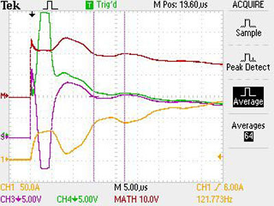
Notice that the horizontal scale on the oscilloscope is 50 microseconds wide, and the vertical scale peaks at about 300 amps. Look at the yellow line that indicates current and see how it ramps up and levels off. Think of it -- a good analogy you’ll probably understand is an amplifier when you test it with square waves. How does it respond to square waves? It’s very similar. We want a fairly steep rise time and we don’t want ringing or any kinds of anomalous behaviors. It’s logarithmic and it’s smooth, and you don’t see any significant ringing on any of the pulses. If we saw any funny behaviors, then this would indicate that the component was reactive. MF: And is it normal to see a voltage drop? CG: Everything has a voltage drop. That’s why this is significant. We can actually measure the voltage drop across power wires that are only a few feet in length. When we were designing the DTCD Analyzer, if we made a circuit of wire on the PCB one inch longer, we would see a measurable difference, objectively, on the 'scope. Let's plug in this Venom3 cord. Now make a mental note. See the yellow line -- the standard cord was below the center reference line while the trace for the Venom3 rises well above it. This indicates a higher quantity of instantaneous current delivery. Also, notice that the red line indicating voltage drop was much higher for the standard cord than you see here with the Venom3 [a lower voltage drop is better]. MF: But you didn’t have this device when you designed these cords, so you were designing based on other aspects of what you knew? CG: But look, I created the concept for this device. The concepts used to create the DTCD Analyzer are the same principles that I have been using for years in the design of our power cords. I created this device so that I could measure current delivery in a very precise manner. I’ll show you something when we get over to the other building that is a simpler device that is used today to test test electrical wiring in commercial buildings.
Power supplies: notes from the graduate seminar fter the DTCD demonstration conducted in real time, we walked over to a meeting room where we spoke for a few hours about measuring what he and I would suspect a majority of serious audiophiles have heard when swapping out power cords in a high-resolution audio system. Gabriel also took the time to explain to me how power supplies work and how that affects power conditioners, power filters and isolation transformers. CG: To understand how any of this works you have to understand how a power supply works in a typical electronic component. All power supplies convert alternating current to direct current. There are two major types of power supplies, the first being a typical linear power supply that needs a large transformer. The other type is commonly called a switching power supply and does not require a transformer. However, they both use high-current rectifiers. A rectifier is a type of electronic switch that turns on and off in time with the frequency of the power line. The rectifier converts the AC input to pulsating DC. The rectifiers are only turned on at the positive and negative peaks of the AC waveform. When they turn on, they charge the storage capacitors in the power supply. So, you see, the power supply turns on and only draws current for a few milliseconds and then it turns off until the waveform reaches the next peak. It does this, constantly turning on and off, like a clock 120 times per second (US power frequency of 60 cycles). MF: Now this will happen in a split second, almost instantaneously, right? CG: Well, it depends on how big these capacitors are. This is why in a big amplifier that has huge capacitors can take to several seconds to fully charge. And that’s why when you first turn them on they pull a lot of current. It's also why some amplifiers can blow the circuit breaker -- or if you take a power cord and plug it into the wall (with the component on) it can arc and burn the contacts. [Even if you didn’t grasp the preceding paragraphs, this is the one that’s key. For more information, read Shunyata's white paper. -MF]
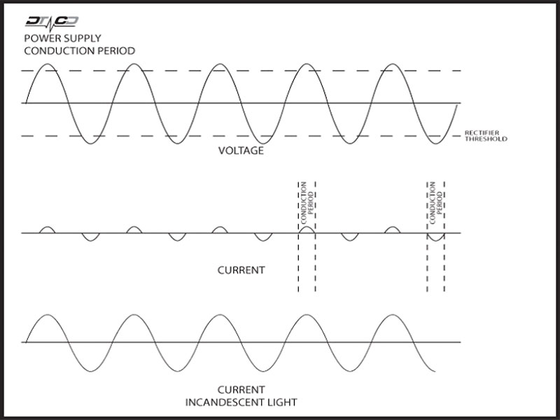
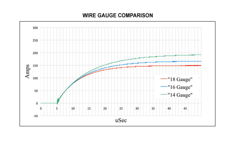
You’ll notice we have our power analyzer over there. If we were to connect it to a typical power supply, the output would be very similar to this chart. The bottom trace shows the current delivery into an incandescent light -- see how it is similar to the voltage waveform in that the light pulls current across the entire waveform? Now look at the top trace that shows the voltage as it appears to the rectifiers in a power supply. Notice that the rectifiers only turn on at the voltage positive peak and negative peak. But if you look at what the current is doing as indicated by the center trace, you would see these little blips: pulls it off the top, pulls it off the peaks, pulls it off the valleys. So it pulls it in pulses. Pulse, pulse, pulse, pulse. . . . Current only flows for narrow periods of time. What does the DTCD Analyzer do? It simulates the power grid in the wall so we can test things in a precise way because the voltage and the current coming out of the wall varies according to the load in the building and what’s hooked up in the building and what’s running at a certain period of time. The voltage can vary from day to day. When we are testing new products, we want to be able to have the same result we have today as we have tomorrow as we have a month from now. We need to have a reliable reference standard. So the DTCD Analyzer simulates the power grid within relative limits. The power grid can deliver a lot of current, so much so that if you decrease the load and the impedance low enough -- like a short circuit -- you can melt the wiring behind the wall. You can do arc welding! The power grid has an incredible capacity to deliver current in an attempt to maintain a constant voltage level of 117V. Now remember the power supply pulls current in pulses, but when I plug it in, the voltage is present here [at the transformer output]. The AC waveform is being applied, but no current is being pulled until those rectifiers switch on. So this is similar to a pressurized system. We’re not sending a signal down a wire. The pressure of the voltage level exists on the line and in the power cord. What determines when the current flows through the cord is the power supply itself. When the rectifier in the power supply turns on, then current is drawn. It is not sent from the power station to the power supply -- it is drawn by the supply from a vast reservoir of current (the power grid). We have this little switch here and as soon as the hammer drops, now current is going to flow. So the device itself is determining when and how hard it pulls on the current, and the power grid is going to attempt to supply as much current as this device will draw -- or wants to draw. What the DTCD Analyzer does is to simulate the pulsed draw of a power supply from a constant-voltage-source power grid. In a real sense we’re simulating how it works in the real world, but in a precise way. Now that you have an idea of what it does, and a little bit about how it works. What can we do with it? One of the things you can do is actually measure voltage drop and instantaneous current delivery in power cords, which engineers have not been able to do with conventional power analyzers or meters. For instance: here are some readings from several standard power cords. We a have typical 18-, 16- and 14-gauge power cords. These are the common ones that are shipped with components today.
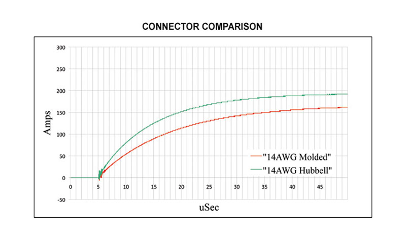
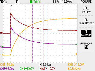
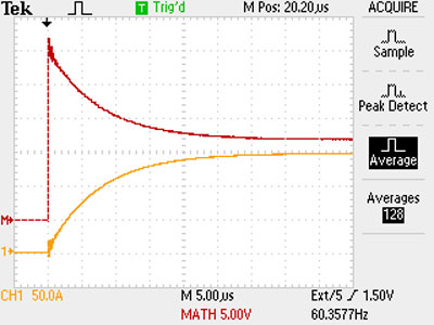
We measured each one. And you’ll notice, as you move to a larger gauge power cable, its ability to deliver instantaneous current goes up. So 18 is the lowest, 16 is higher and 14 is higher yet [the wire gauge number is inversely related to wire size]. Intuitively, most people would say, "Well, that makes sense." But many engineers would argue that as long as the cord can carry the continuous current rating it makes no difference. Unfortunately, some electrical engineers will dismiss power cords by taking out a simple volt meter and say, "Look, it says 117 volts on this one! Look, it’s 117 volts on this one! They’re all 117 volts, so they are all the same." And even engineers who were smart enough to use current probes -- they’d hook up a current probe and say, "Look, both power cords read the same current level." What they are not taking into account is that power supplies pull current in pulses. The test equipment that they are using actually average the readings over one or more AC cycles. What we’re looking for specifically is what happens during the conduction period of a single cycle. This brief period of time is the only relevant measurement since it is the only period of time when the cord and power supply are actually drawing current. But the DTCD Analyzer shows that it does make a difference to instantaneous current, and it is measurable and it is significant. We’re talking about the difference between about 190 amps instantaneous compared to around 148 amps instantaneous. So it’s not 1%, .1%. It’s significant -- it’s 10%, 20%. This demonstrates that we can measure differences between power cords of various sizes. Well, the next thing that comes to mind is -- does the connector make a difference? Here we took a standard 14-gauge molded power cord that’s shipped with many amplifiers today.
We took one of them and just cut the connectors off and put a set of good Hubbell connectors on it. Now, using the DTCD Analyzer, we measured the standard cable and the identical cable with the custom connectors. The red line represents the standard molded cable and and the green line is the cable with the Hubbell connectors. Notice the difference in current delivery capability -- the same cable -- just connectors have been changed. MF: But why would that be? CG: Because the quality of the connector, the quality of the connections, the quality of the contact to the wire are inferior in the molded cable compared to this cable, where we custom-terminated the cable. The connectors make a difference -- how you terminate them. Do you crimp them? Do you solder them? Was the connection done correctly or not? Now obviously this molded cable was not defective, because we did multiple tests on multiple cables and they all tested the same. But the quality of the connection was superior with the Hubbell connector. You see, we can measure the difference between connector contact points. And this also was significant. This was 190 amps versus about 160 amps. If you look at it (the molded plug connection) physically, it’s like a blade. It’s designed so that they push the wire between the blades and the blades cut the insulation and so you have a knife-edge contact. And that doesn’t have as much surface area as you would with a Hubbell, where you strip the wire and you put it in there and you screw it down or you solder it. Because we can now show significant current differences between power cords, some people would argue, because everybody likes to argue, "Well, then obviously, if you use a bigger wire it’s going to have more current capacity and obviously if you use a good connector it’s going to be better." And listen! That’s been our whole point all along! The wire matters, the connectors matter, how you make the connections matters. Look, the only point we are trying to make is we can measure these things now, which people haven’t been able to do, and we can now prove it. So get the black cables out. You know, even if you take the black wire, cut off the connectors and put on a decent connector on. Do that! This next graph demonstrates the difference that wire geometry can have on current delivery.
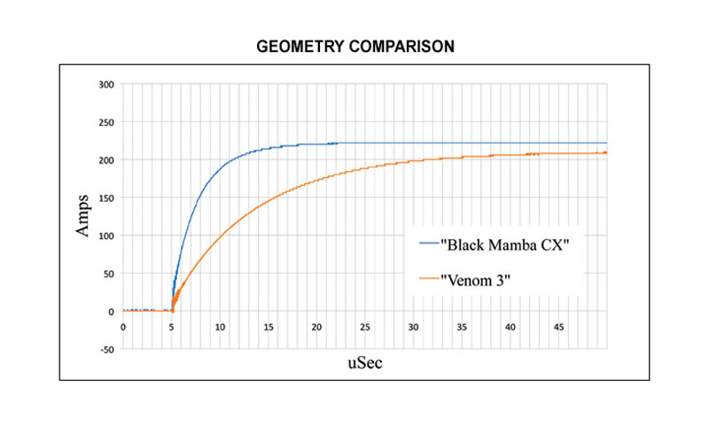
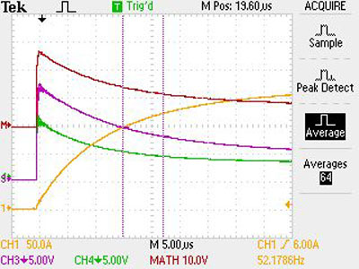
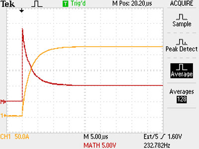
We make the Venom3 power cord and we make the Black Mamba CX power cord. One costs about $100 and the other one costs about $600. Both are 12-gauge power cords and both have great connectors -- so why would anyone buy the expensive cord? Well, look at this graph: this yellow line represents the Venom3, and the blue line represents the Black Mamba CX. The difference is only due to the differences in wire geometry and complexity. The Black Mamba CX is a Helix design with counter-rotating conductors around a virtual tube, which you saw being manufactured downstairs.
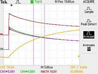
You’ll notice something very significant about a CX cable’s measurements: look at the very steep rise time in response to current. What’s significant here is not where this ends up; it’s the area under the curve. You look at the area under this curve and this is vastly superior. Even when they stabilize after the pulse, the Black Mamba CX still conducts more current in a steady-state place, but look at the difference here in the first part when the rectifiers first turn on and the difference is huge. It’s almost 150-amps of difference in the first part of that curve. That proves geometry makes a difference. Those are some of the first measurements we’ve done, and there is a wealth of explanation on our website. We will be evolving DTCD to test switches, breakers, fuses. You know, one of the things people talk about is, "Does the wire in the wall make a difference?" And you know, it can be easy to swap a CD and say, "Wow, this CD player sounds better," but what if you’ve changed outlets? Well, it’s hard to change an outlet and to go back, so you think you heard something, but maybe it had to do with the equipment warming up, or stabilizing and you say, "Well, I’m not going back because it’s too hard to change the thing out." We create test jigs where we can swap things out in real time and we can test ten of them in five minutes and then you can go back and compare them very precisely. But what we’re going to do is to create a false standing wall and we’re going to put a circuit panel in it, and we’re going to take different types of Romex and different types of in-wall wiring and then with the DTCD Analyzer we’re going to test different types of circuit breakers and different types of wire. What happens when you go from 14-gauge to 12-gauge to 10-gauge wire in wall? We’ll actually be able to show that for a 100-foot length of wiring. Then we will have actual measurements of what you gain in performance by replacing the in-wall wiring or outlets or different types of electrical breakers. In a moment I’m going to show you how we test the current-delivery capacity of a circuit within your wall. You’ve never heard anybody in the industry being able to test what your wall outlet is capable of delivering, which is determined by the wire in your wall, your circuit breaker, your panel, the main cable that goes from your house to the transformer, and the transformer itself. And people say, "Well, if you put in a dedicated circuit it’s superior. But how do you know? Did you measure before and did you measure after?" We can actually do that, and we can show you how to do that without a DTCD Analyzer. [Caelin does a demo showing how to measure the actual current-delivery capability of a live circuit.] Using DTCD to test power conditioners CG: We’re going to test power conditioners now. To energize the conditioner we’re going to connect a power cable that feeds it power. We made custom test cables that are exactly 30" long and then we design them in such a way that we can plug the cables into one another with no power conditioner between them, because obviously if we can measure a 1" difference in wire, measuring a power conditioner in series with a power cable would be unfair if they were not the same. We want to use reference cables to make sure they are not part of the equation. This is our baseline [below]: The custom test power cables plugged into one another without the power conditioner in the circuit. This graph shows the corresponding current capacity and the voltage drop.
Take note of the purple trace and the green trace. Now remember, this shows the voltage drop of the hot wire and the neutral wire individually, and notice they lay right on top of one another and that they exactly coincide. That’s because there’s no difference between how much voltage drop is in the hot versus the neutral. They are the same. That becomes important later. Now here is a Hydra 4 [above], which is a product we make. Now you’ll notice that if I were to overlay the graphs, you’ll see that we lose a certain amount of instantaneous current capability, which is what you’d expect. But the other thing that’s interesting is, notice this -- that there’s now a difference in the voltage drop of the hot versus the neutral. They diverge. MF: Why is that? CG: The hot in the Hydra 4 has a magnetic circuit breaker in it. The voltage drop across that circuit breaker, that’s what accounts primarily for this difference. MF: What’s the significance of this? CG: Since they are both linear and there are no abnormalities in it, for the power supply, probably nothing, other than that it contributes to the total voltage drop across the conditioner. If we were to take the circuit breaker out, we could get better instantaneous current delivery, but then we wouldn't have any over-current circuit protection, so that would be a bad thing. Yeah, we lose some current-carrying capabilities across the breaker, but if we were to show the difference between a magnetic breaker and a common thermal, you might be surprised. Okay, here’s a Hydra 8 [below], and you’ll notice something interesting about the Hydra 8 versus the Hydra 4. They are actually very similar, aren’t they? As a matter of fact, they are almost identical. Everything is linear about the curve, the voltage, even the maximum current levels they reach are similar, and that’s because they were both designed to maximize instantaneous current delivery. Where you see a difference, and this is what you astutely pointed out, what about noise? Each of these has a filter in it. And this part where the pulse starts to conduct current, you see ringing. You see the ringing there?
MF: That’s on the 8. CG: That’s on the 8. Why does this ringing look larger [than on the 4]? It’s because the 8 has much more filtering than the Hydra 4, which gives it more noise reduction, but it has a slight bit more resonance. But you’ll notice something about the ringing in both cases. It’s well controlled and it dampens very quickly to virtually zero in just about a few microseconds. Okay, that will become important in about a minute. And here’s why: remember the power conditioner that we should cross out the name [we will not divulge it here]? Here are the measurements. This represents power-conditioner design that utilizes very large capacitors. Some companies may use the philosophy of, "If one capacitor is good, two must be better. If one microfarad is good then ten should be better than that. One hundred would be fantastic. How many can we get in the box?" So, this is the DTCD Analyzer readout of that device. Now, not being particularly knowledgeable or technically adept, anybody can look at this and go, "Oh, my God, you’ve got to be kidding." Now, here’s the best analogy I can give you. Consider these power-impedance curves as analogous to the impedance curve of a speaker. Look at the power-impedance curve of the Hydra 8 -- notice it’s linear and it doesn’t ring. It is very well controlled. Now compare it to the power-impedance curve of this [unnamed] conditioner. Now, imagine you have a speaker and it has a wildly differing impedance curve that drops to 1 and shoots up to 100 ohms. It’s going to be very hard on the amplifier. This device is going to be hard on the power supply that you plug into it. Look at its current waveform. It starts to conduct current, and then it flattens out, and then it actually decreases current and then it increases and then it decreases. But check this out. What is this [pointing to the trace]? This is actually a very long oscillation or resonance. Remember I told you capacitors can resonate? This is a very profound resonance. And you’re going to have current resonance within the power supplies of the devices that you connect to this conditioner. It will be unpredictable, but you could, depending upon the power-supply design, set the power supply into resonance or oscillation. Now, remember this is the hot and this is the neutral [pointing to green and purple traces]. Look at how they wildly diverge here: There’s a dramatic drop in impedance -- a huge drop in impedance on one and at the same time a huge increase in impedance on the other. The voltage drop goes really low and the impedance goes really high, so across the rectifier you’re getting this massive drop in impedance and corresponding massive high impedance on the other side. Even if you sum them together [red trace], look at the resonance. This is why the performance for those using this device will be highly dependent upon how the power supplies they plug into it are going to respond to the reactive load they see. I would say this would be a highly reactive power conditioner. Now you understand why I say look at these -- they both look similar [the Hydra 4 and 8 graphs], but they are extremely well controlled. We do have filtering in the Hydras, but it is very linear and dampens any slight ringing very rapidly. This is not to condemn this other conditioner manufacturer. What these people are doing is using conventional filter design. They are using an L filter or a T filter or a Pi filter. In conventional engineering terms, that’s what you’d want to do because they want to create a low-pass filter. Are they impeding current flow? Oh, yeah! Not only are they impeding it, now they are imposing resonances on the current flow and it’s making it highly reactive to anything you hook up to it. By contrast, we don't believe that a low-pass filter design is advantageous to high-end power-conditioner design. We strive to maximize instantaneous current delivery while minimizing reactance. Now, let’s look at the Triton. Let's see why the new generation Triton may be better than the Hydra 8. Because, look, if [brand "X"] is your competition, the Hydra 8 looks pretty damn good. Here’s a Triton compared to a Hydra 8. Well, the first thing I see is that we’re back to nice linear power-impedance curves, and I also notice that the Triton has a bit less instantaneous current flow than the Hydra 8. Now why is that?
Now, remember I said ideally you want to have the maximum current flow possible, so if you are going to give some of that up, what are you getting for it? This voltage drop is caused by the massive noise-isolation chambers and associated wire within the Triton. So we’re giving up some of the instantaneous current, and in return we benefit by the reduction in noise provided by the NICs [noise isolation chambers]. Furthermore. . . . MF: I can see the reduction in ringing. CG: There you go. You homed right in on it. Look at this: the Venom filters in the Hydra 8 are obviously superior to just common capacitors. This is what we could do pre-DTCD. But with DTCD analysis we were able to optimize the noise-reduction profile of the MPDA (multi-phase differential array) filters that are used in the new Talos and Triton conditioners. Notice that by comparison the ringing is virtually imperceptible and it’s almost gone, within just a nanosecond of the pulse. It’s like one, two, three very small oscillations and then it terminates completely. MF: And this is also closer. CG: Exactly right. And you’ll notice the impedance curve and the voltage drop at the hot and the neutral also very closely match the baseline. Let me show you just one other thing. This is fascinating. Remember, this is just wire. Look what the MPDA is capable of doing. The wire itself, rings, it has a resonance, but notice that the MPDA can actually eliminate some of the ringing inherent in the wire itself because of the inductance of the wire. Not only can it reduce noise, it can actually reduce the natural ringing caused by the inductance in the power cable itself. We’re giving up some of the current capacity to gain the ability to eliminate these noise components, and that’s what you hear. MF: And that’s what you hear. You do hear it too! CG: And it’s right around the leading edge of that transient where you hear it, and that’s why everything sounds more linear. MF: That’s the first thing I heard as soon as I plugged it in. But the Hydra V-Ray, I have to say, sometimes I felt it added. . . CG: An edge. MF: Yes. CG: And that edge, you’re hearing this [points to graph, shown above]. Well, you said you didn’t like that, but this is typical. MF: I tried this one [another brand power conditioner], but I heard no benefit -- just another power cord and a box between my electronics and the wall. CG: With the right piece of equipment plugged into this, it could cause very severe sonic artifacts. Remember, this is not connected to an amplifier power supply. This measurement shows what the power conditioner it is doing all by itself. Imagine when you connect it to one, two, three or four power supplies and they are all different and they are all interacting with these complex impedance curves. There it is. The reason I can say we have made a superior product is because I’ve already tested every kind of capacitor -- I’ve built my own capacitors. I’ve tested every kind of transformer coil. We’ve built our own handmade, single-wound, air-core coils, transformers, so every type of power concept I’ve tested. I know what they do. And now we can measure what they do. Otherwise we wouldn’t have been able to achieve what the Hydra Triton and Talos can do without the benefit of DTCD. We also do noise tests when designing power conditioners. We do severe noise tests. We hook up the power analyzer and we hook up the power conditioner and we take a paper shredder and we plug it into the wall and you look at the power analyzer and what you see on the waveform are these spikes like this [draws a series of lines attached to sine wave]. It is horrendous. And this is our worst-case test. And whether you run it through a Hydra 8 or this device [competition] or a Talos the noise will be reduced. But at what cost? CG: With this [points to the curve of a competitor’s power conditioner], the price is a massive reduction in current capacity and the introduction of these complex resonances. With a Hydra 8, you do not lose much current-carrying capacity. You get the noise reduction, which is compelling because you can hear deeper, but as you have the Hydra 8 or any component over time you start to hear their signature. The Hydra 8's signature was on the transients; you could hear this extra edge, this extra bite and some people associate this with "That’s just good; it’s not rounded off." But over time I recognized that it was artificial -- that it just doesn’t belong there. So with the development of the Talos and the Triton, we’ve been able to significantly reduce that form of distortion from an already excellent product. Before DTCD, it was a matter of the talent of the designer, the intuition of the designer, the ability of the designer to hear using their audio systems. I’ve brought it out of that subjective realm and brought it into the realm of, look, I can show you why one power cord might be better than another one. I can take a competitive cord and it might measure just as well as that Venom3 cord, but that won't necessarily tell you that it sounds better. There are other things involved. But look, this is the first pass. We’re starting to pierce the veil. This is the first step along that path where we can now measure differences, and not subtle differences, because you don’t hear subtle differences when you plug in different power cords. You hear big differences. These [hands on the measurement graphs presented during the discussion] are big differences. This [pointing to Triton] is a big difference. MF: Slightly different subject: the cable elevators. Skeptics often send me e-mails berating me for one thing or another, but when they are not calling cables a scam, they second it with products that raise off of the ground, the "scam" cables. CG: It’s all on the website. First of all, we have been granted a patent on the concept. You can read the patent. It’s exactly what I say it is. There are only two things involved. There’s only resonance and static electricity. Everybody knows about resonance. There are many people who accept resonance and its effects upon a component. But, they say, "Why would you put a cable elevator under there?" Well, to reduce the vibration coming from the floor. Well, how do you know it affects the electric signal going through the cable that’s moving near the speed of light? I could turn around and make the same arguments and say that doesn’t make any sense. It vibrates the conductor, it vibrates the dielectric and that induces some micro-voltage onto the signal. Okay -- wow. Theoretically that’s true and that is a measurable effect, but then they ask, "Can people really hear that?" Well, you and I know that in the context of a high-end system there are things that you can hear that you cannot measure. Measuring equipment is not up to the challenge of discerning very small differences that we can hear. And what audiophiles call big differences -- in reality if you could measure it, they are not big differences at all. They are small and they are subtle. But look, when we were cavemen out in the forest and foraging for food and there’s a mountain lion out there, the slightest, subtlest auditory noise was the difference between life and death. You hear the snap of a twig and instantly the brain can calculate what direction it came from. How far it was. Was it a soft paw? Was it the hard paw of, for instance, a deer? All of those things the brain can calculate, and those senses evolved over millions of years. The brain’s ability to discern and perceive far outstrips the ability of test equipment to measure it. When somebody comes to me and they say, "I don’t believe in that," I say to them, "It's your right; you don’t have to believe it." You can believe your ears or you can trust the measurements; it's your choice. Look, if you’re willing to take the time to actually try it, if you try it and it works in your system, then great. Then, go and read what I have to say and go, "Wow, there’s a reasonable explanation." MF: To which I say amen and thank you! |
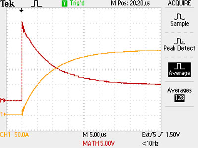
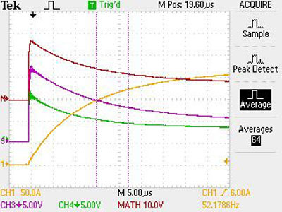
 Now here’s one of our
better cords [right]. Notice how much faster it responds. Remember how I said that it was
similar to a power-amp square-wave response test? Look how much steeper the response to
current is. The current rises far faster than either of the other two cables, and
that’s one of the reasons why a Black Mamba performs better.
Now here’s one of our
better cords [right]. Notice how much faster it responds. Remember how I said that it was
similar to a power-amp square-wave response test? Look how much steeper the response to
current is. The current rises far faster than either of the other two cables, and
that’s one of the reasons why a Black Mamba performs better.